Functional Test
PEM FUEL CELL STACK ASSEMBLY MODULE EMPTYING & FILLING TESTING
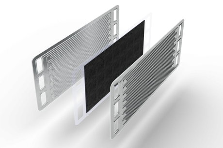
Cooling circuit is an essential part of the PEMFC stack, since it allows the re-circulation of the coolant fluid through each bipolar plate of the assembly. The aim of the cooling circuit is to monitor the temperature of the system during operation and keep it inside the specific range, to achieve the efficiency and ensure the durability of the MEAs. A deionized fluid is usually employed, in order to minimize the electric risks related to the high voltage produced by the stack during operation: deionized water (< 10 uS/cm) or a mixture of it with glycole are the two most common solutions.
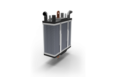
After the complete assembly of the PEMFC stack and after the leak testing of all of its circuits, including the cooling circuit, an important step is to fill the latter with coolant fluid for the first time. In fact, it is important to assess the proper functionality of the system.
So, the filling and emptying station is a relevant step in the end-of-line testing of a PEMFC stack, but it is also useful for preparing the stack for further testing procedures (e.g. HV testing with filled cooling circuit).
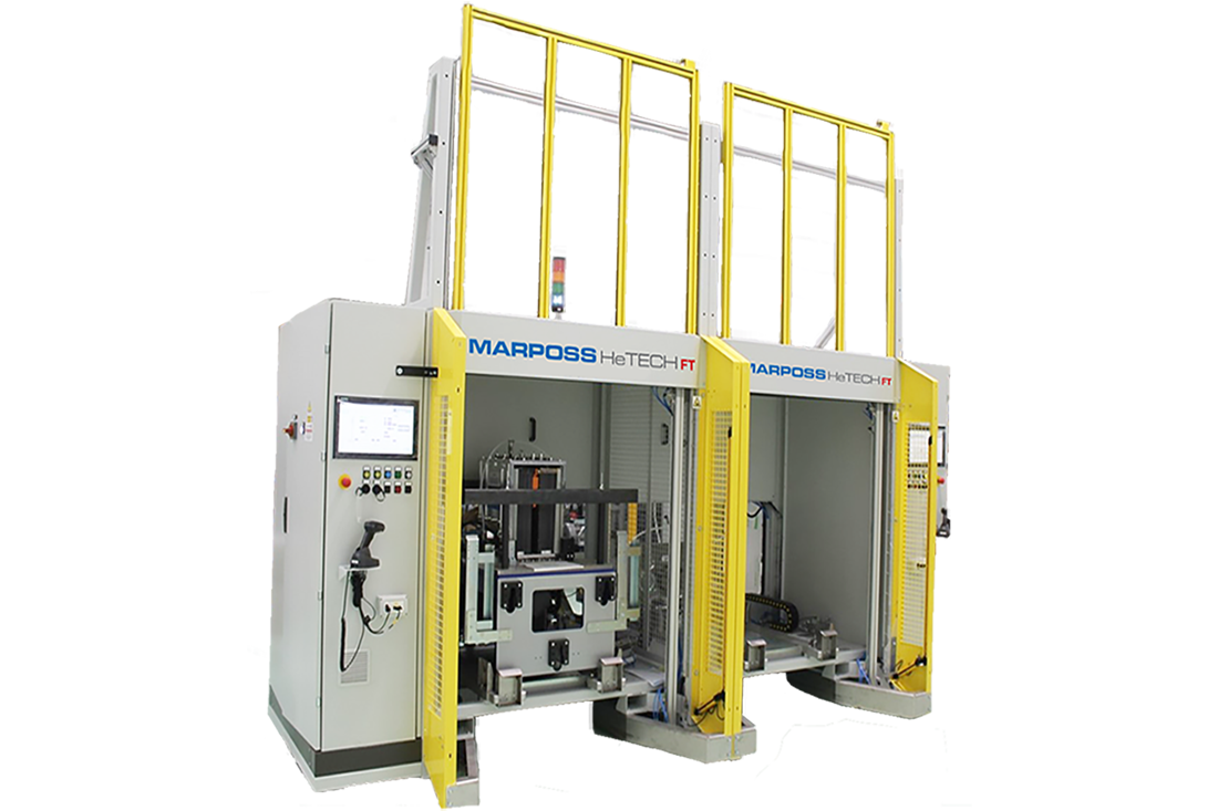
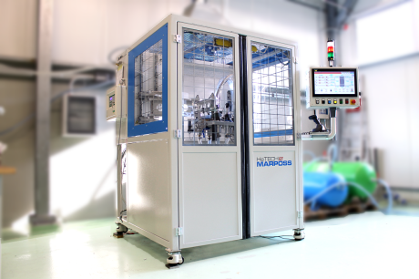
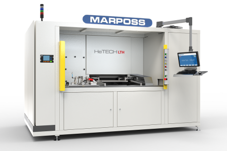
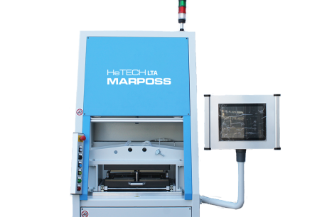
Double station Emptying/Filling test for PEMFC SAM (Stack Assembly Module), Single Stack and Two Single Stacks, with manual loading/unloading (a console provided by the customer allows the integration of the DUT with the test bench)
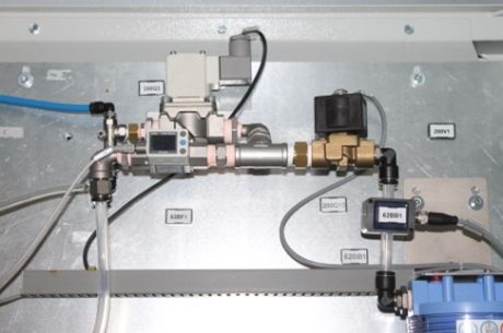
Principle of measurement: bubble detection through water flow (both counting and diameter measurement), based on ultrasonic method.
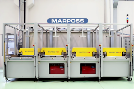
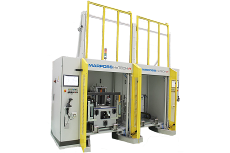
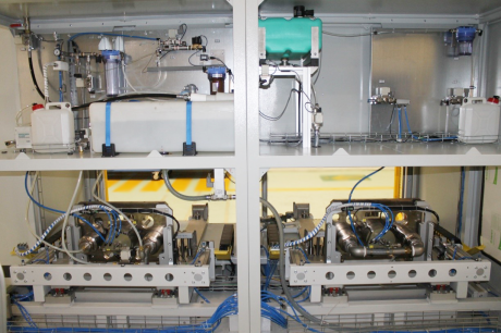
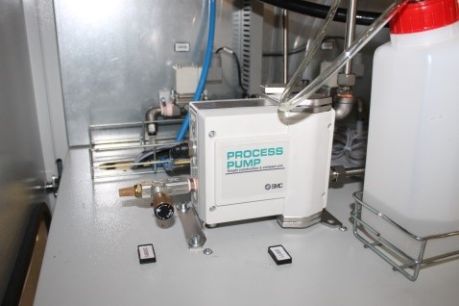
The bench provides two independent stations, assembled on a welded painted steel frame with cover panels and automatic door. The cabinet containing the electric switchboard is on the left-hand side of the bench, while the pneumatic process components are located on the right-hand side. All of the water circuit components, such as water tanks and pumps, are located in the upper back part of the bench. The access to the stations is protected by safety light curtains. Only electrical supply, water and air supply are needed to run the machine.
The two stations are conceived to be completely independent and to be able to work at the same time as well as asynchronously. Thus, both of them are provided by dedicated PCs, HMIs, PLCs and DMX readers.
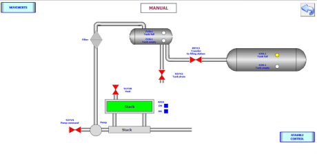
Water management is independent as well, with one large tank for water filling (120 L) and a smaller tank for collection of water disposal after water emptying (30 L). Both of them are equipped with their own set of full/empty sensors, managed by the PLCs in order to allow the automatic operation of the two stations. A dedicated valve allows the water to flow from the emptying tank to the larger filling tank. The management of all the system is carefully designed in order to optimize the consumption of deionized water, by minimizing the water supply and minimizing the water disposal out of the bench.
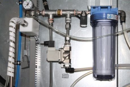
All of the water circuit and its components are suitable for deionized water. A set of devices for deionized water management and electrical conductivity control is also installed in the circuit, allowing the continuous measurement of the rate of water deionization and keeping it under the maximum allowed threshold (10 uS/cm). Two water pumps are installed, one for the water re-circulation inside filling station circuit, one for water disposal in the emptying station.
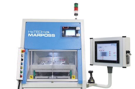
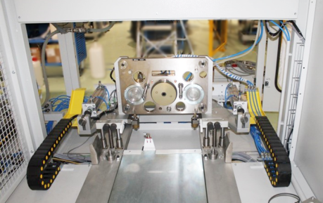
The fixture is automatically actuated and allows the coupling between the bench and the interface of the stack under test, by way of a multi-coupling plate.
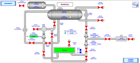
The bench incorporates two industrial PCs which perform HMI functions while supervision of the process is made by two PLCs. The software is configurable so that it is possible to:
- Set machine parameters
- Create different recipes, according to required test parameters
- Manage the automatic cycle as well as the manual cycle
- Set counters and production data
- Manage levels of access
- Dedicated electric cabinet
- Easy access to process circuit by way of front doors
- Configurable HMI touch screen interface
- Push button panel and light signals for easiness of the operator
- Two independent stations
- Optimized water management
- Deionized water circuit and management (sensors and active deionizing unit)
- Temperature sensor for safe water management
- RFID System and Datamatrix reader for traceability purposes
- IT Interfaces are provided and MQTT (Message Queue Telemetry Transport) and TCP/IT (Transmission Control Protocol/Internet Protocol) transmission protocols are implemented
- Water flow rate: 10 L/min
- Water pressure: 1 – 2 bar abs
- Water electric conductivity: < 10 uS/cm
- Bubble detection: > 3 mm diameter
- Water tanks volume: 120 L + 30 L