Leak Test Air
PEM FUEL CELL STACK ASSEMBLY MODULE NITROGEN LEAK TESTING BY MASS FLOW MEASUREMENT
Leak testing is an essential operation in the PEMFC cell production process, since it verifies that no leakage is associated to the electrochemical system, either internal to the system itself or towards the outside, simulating real operating condition.
After the complete assembly of the PEMFC stack, a crucial step is to verify the tightness of its three main circuits (anode, cathode and coolant), both towards each other and towards the external environment. In fact, even if the single components (MEAs, bipolar plates, gaskets…) have been already tested during their production processes, the overall assembly of them could bring additional sources of leakages. Avoiding them is crucial to assess the safety and the efficiency of the system once operating.
Accordingly, the tightness of the PEMFC stack is of paramount importance to ensure the efficiency and the long term reliability of the fuel cell system.
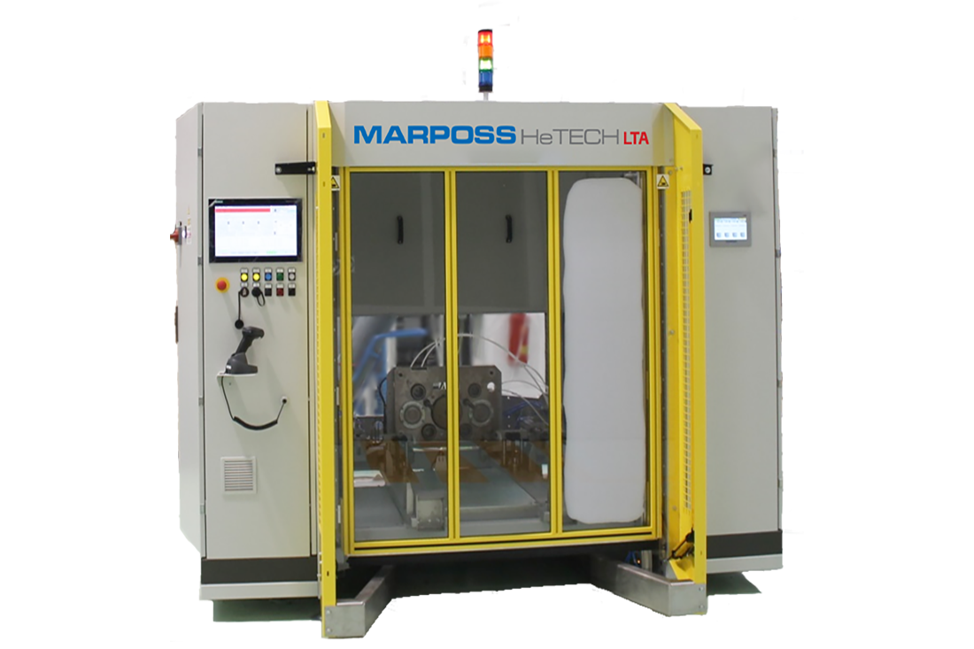
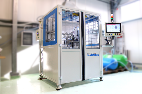
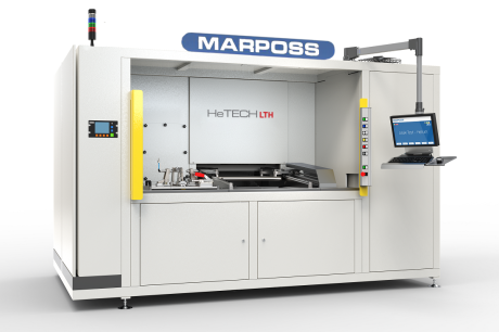
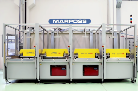
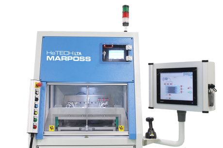
Single station N2 leak test for PEMFC SAM (Stack Assembly Module), Single Stack and Two Single Stacks, with manual loading/unloading.
Principle of measurement: nitrogen mass flow measurement, by way of Tecna TM3PF measuring devices.
The bench provides a single station, assembled on a welded painted steel frame with cover panels and automatic door. The cabinet containing the electric switchboard is on the left-hand side of the bench, while the process components, including the measuring devices, are located on the right-hand side. The access to the stations is protected by safety light curtains. Only electrical supply, air and nitrogen supply are needed to run the machine.
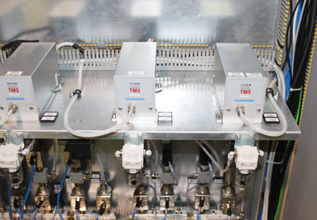
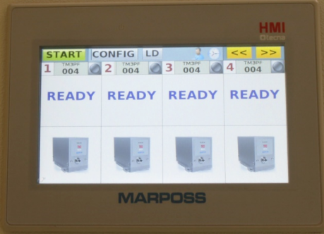
Four different measuring devices – with a unique touch screen display at sight, so that it is possible to look into the values of pressure/flow rate of the test phase – are installed in the bench: No. 3 devices allow the of the three circuits towards the environment as well as the; a foruth measuring device monitors the cumulative leakage of the stack towards the environment.
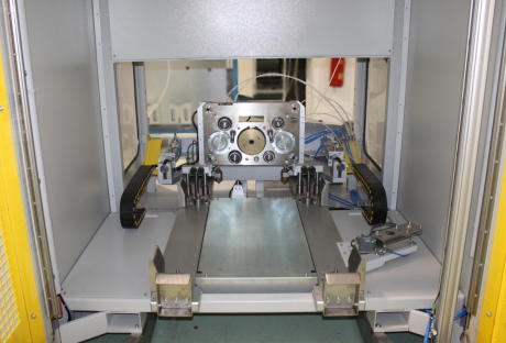
The fixture is automatically actuated and allows the coupling between the bench and the interface of the stack under test, by way of a multi-coupling plate.
The bench incorporates an industrial PC which performs HMI functions while supervision of the process is made by a PLC. The software is configurable so that it is possible to:
- Set machine parameters
- Create different recipes, according to required test parameters
- Manage the automatic cycle as well as the manual cycle
- Set counters and production data
- Manage levels of access
The bench is also provided with a dedicated master OK/NOK, which integrates different calibrated leaks, so that it is possible to guarantee the accuracy of the measurement performed by the machine.
The master cycle can be done at the starting of the machine, at the beginning of each shift or whenever it should be better to carry out this calibration procedure.
- Dedicated electric cabinet
- Easy access to process circuit by way of front doors
- Configurable HMI touch screen interface
- Push button panel and light signals for easiness of the operator
- High accuracy of the system
- RFID System and Datamatrix reader for traceability purposes
- IT Interfaces are provided and MQTT (Message Queue Telemetry Transport) and TCP/IT (Transmission Control Protocol/Internet Protocol) transmission protocols are implemented
- Test Pressure: 0.5 bar rel and 2 bar rel
- Leakage flow rate range: 3 – 90 sccm
- Measuring time: 5 s